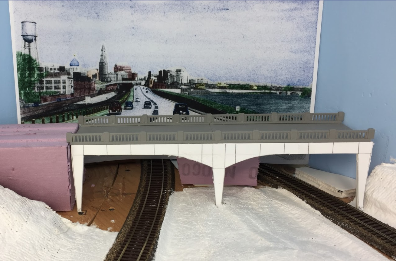
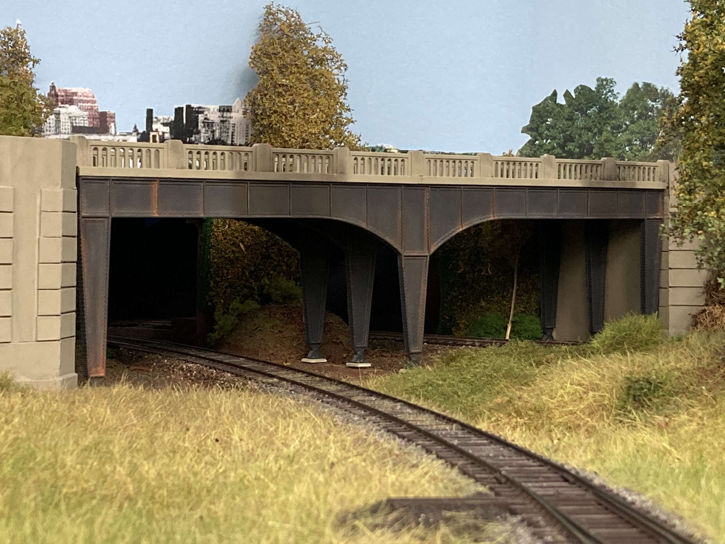
After my success designing the DL-109 winterization hatches in Sketchup and successfully having Shapeways print them, Chris Adams asked if I could design and print some bridge steel to place under the Rix Highway bridge pictured here. Chris wanted the bridge to be used as a view block for the northern end of the Valley Line where it passes through the backdrop to Hartford staging.
Chris had already drawn a mockup of the steel to show me how he wanted the steel to look. He also suggested that we design and print one set of bridge steel to use as masters for resin casting three more sets for a total of four sets.
Fresh off my success with the DL-109 winterization hatches I was eager to start on the next project.
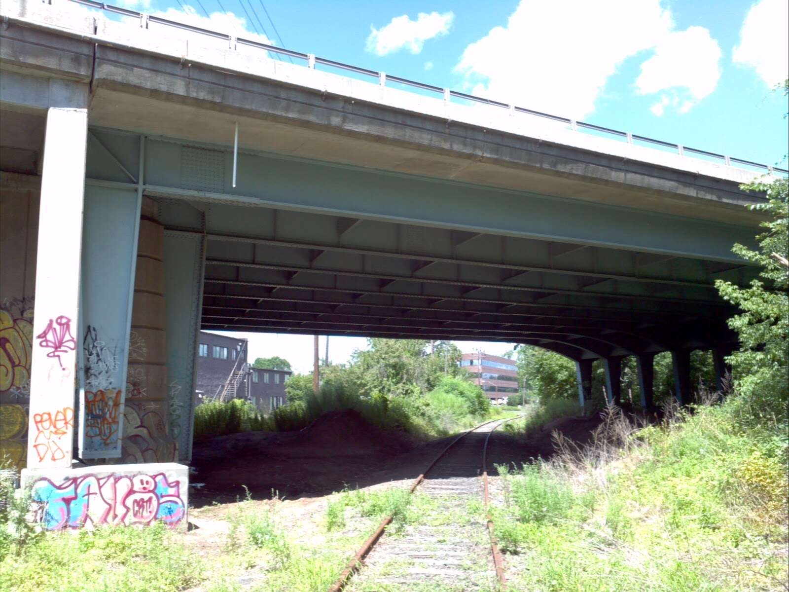
Chris also sent me some photos of the prototype bridge where it carried Rt 15 over the Valley Line in Wethersfield, CT. The plan was to use the photos to design the bridge piers for both sides of the bridge, the shorter center pier, and the left and right girders so they fit under the Rix bridge like the drawing Chris drew for the mockup.
I knew what length I needed to make the bridge steel, 100 HO scale feet long to fit under the bridge. But how was I going to size the bridge vertically?
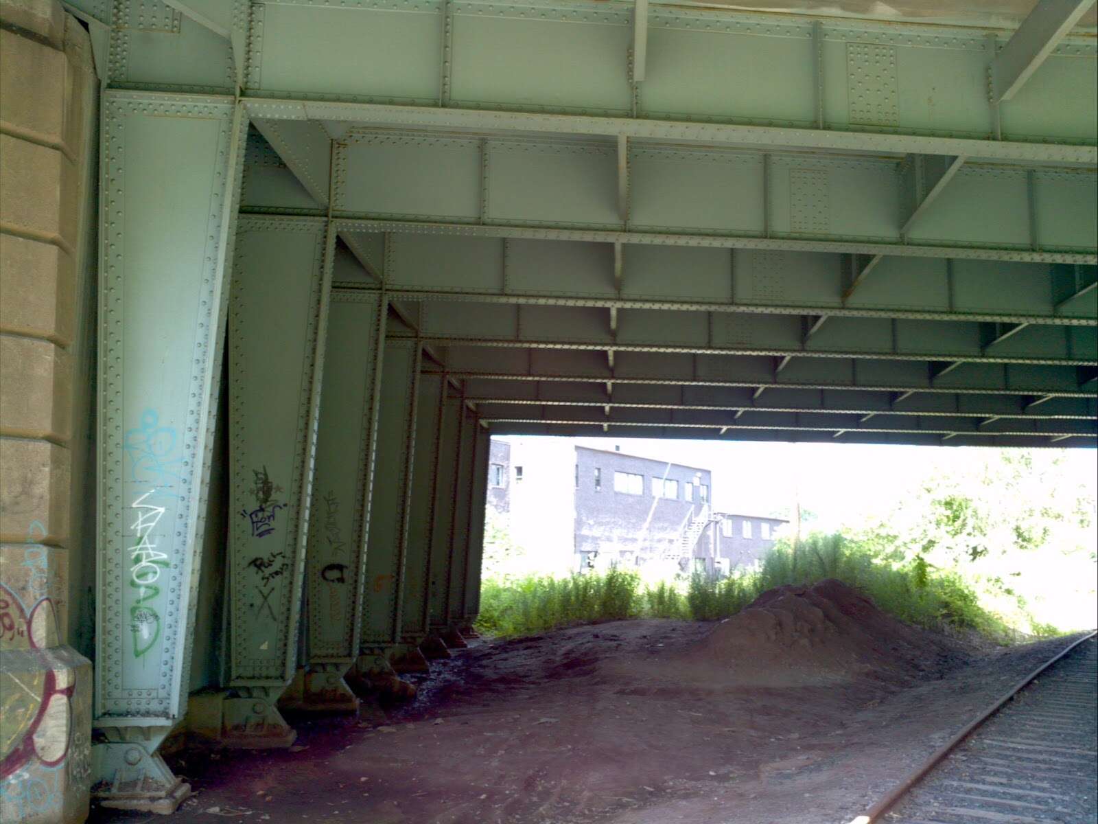
It was fairly easy to figure out from the photos. I knew the gauge of the track was 4′ 8-1/2″ so I could measure the track gauge the same distance from the camera as the vertical pier, and apply the same ratio to the vertical pier. I calculated the vertical dimension of the pier to be a little over 17′ in HO scale.
When I told Chris this, he said his mockup measured just about the same height. I was thinking that was a neat trick to get a scale dimension from a photograph when you have no dimensions.
Original photo of the pier
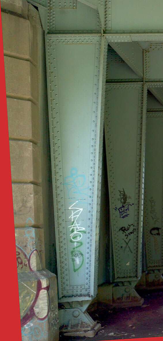
Photo squared up and imported into Sketchup
The next thing I needed to do was start laying out the vertical piers. To do this I started with a photograph of the left vertical pier.
I used Photoshop to square up the photo by using Perspective Warp. Then I imported the photo into Sketchup, rotating it to align the top of the pier with the horizontal axis. Then I started overlaying straight lines on the edges of the pier. I scaled it to the vertical measurement I calculated earlier. Then I extruded 2D surfaces to make the pier a 3D solid.
Then I created a solid component for the rivets. It was pretty easy to lay out an array of rivet components along a guide line added in Sketchup.
I was able to rotate the left pier 180 degrees along the Z axis so I could use it for the right pier without having to design the right pier separately.
I designed the center pier and the left and right girders similarly. Once the design was complete I changed the backs of the parts to be flat so Chris could make one piece mold for resin casting multiple additional sets.
I originally had the parts printed by Shapeways. With Shapeways in bankruptcy in 2024 Shapeways is no longer an option. Any of my models can be printed on my resin printer.